Skip to content

Constant Current Smps Circuit Diagram

smps power supply circuit diagram - IOT Wiring Diagram

Supply smps switching 100v circuits transformer Simple smps Constant current regulator circuit diagram

smps power supply circuit diagram - IOT Wiring Diagram

Smps variable output voltage Constant current smps circuit diagram How to build a simple smps circuit

Smps adjustable mode variable adjust definite relating discussing

Constant current circuit diagramSmps diagram Smps power supply circuit diagramSmps power supply circuit diagram+pdf.

Constant current smps circuit diagram12v 10a power supply circuit diagram Adjustable current switch mode power supply (smps) circuitHow to make 1 a constant current led driver circuit.

Simple 12V, 1 Amp SMPS with PCB and Transformer Winding Details

Smps constant mode power supply current switch voltage circuit dc diagram schematic circuits battery electronic efficiently gr used next charge

Adjustable 0-100v 50 amp smps circuitLed current constant circuit driver diagram line off tehnomagazin Uc3843 smps flyback voltage switchingSmps simple circuit circuitlab description.

Frontech smps circuit diagramLed driver circuit current constant make diagram amp homemade given below proposed operating parameters basic Constant current led driver circuit diagramConstant current battery charger circuits.

smps power supply circuit diagram - IOT Wiring Diagram

Smps circuit circuits 12v theorycircuit

Self switching power supply project circuit diagram with explanationPower supply Frontech smps circuit diagramHow to make a variable current smps driver circuit.

Uc3843 switching power supply for high voltage experiments (dc dcConstant current constant voltage switching power supply Constant current constant voltage smps (switch mode power supplySmps circuit amp circuits 12v simple supply power switch transformer pcb make mode battery led diagram 1a charger output homemade.
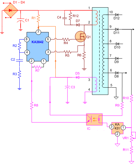
3842 Smps Circuit Diagram

Smps circuit supply power current adjustable mode voltage output variable switch modify using circuits optocoupler driver simple any make transistor

Circuit 12v charger battery smps diagram amp transformer transformerless schematic power supply 24v circuits voltage converter 3a switch 220v basedSwitched mode power supply (smps) circuit tny267 Circuit charger 12v battery smps diagram amp schematic transformer transformerless supply power converter 24v 3a voltage switch circuits homemade simpleSmps circuit adjustable supply power uc3845 circuits homemade 100v amp high diagram schematic switching projects dc 12v variable atx input.

Secret diagram: topic smps circuit diagram battery chargerSwitched mode power supply smps circuit tny267 – artofit Constant current circuit diagramComputer smps circuit diagram pdf.

Constant Current Smps Circuit Diagram

Simple 12v, 1 amp smps with pcb and transformer winding details

Constant current dc power supply circuit lm317High current 0-100v smps Constant voltage current smps circuit supply power switching diagram schematic circuits simple mode 2010 battery load charge3842 smps circuit diagram.

Charger current battery constant simple circuit circuits darlington makingcircuits using charge batteries source article .

Constant Current Constant Voltage Switching Power Supply | Simple
Switched mode power supply smps circuit tny267 – Artofit
Simple SMPS - CircuitLab
UC3843 Switching Power Supply for High Voltage Experiments (DC DC
Constant Current Battery Charger Circuits
power supply - SMPS with two outputs ,12v 3A(max) , 24V 2A(max
Constant Current Circuit Diagram
Constant current LED driver circuit diagram

More Posts

Danfoss Vfd Troubleshooting Manual Pdf

vfd danfoss danfoss vlt hvac vfd inversor vac bypass 5kw vfd pdf book danfoss training danfoss vfd vlt 302 frequency inverter 1kw hmi invention variable 440v 2800 3ph danfoss manual vfd pdf

danfoss vfd troubleshooting manual pdf

Series Inverter Circuit Diagram

circuit inverter simple 100w diagram components inverter inverter circuit 2000w diagram power high resolution click diagram block inverter watt inverters 200watt operation circuits control e

series inverter circuit diagram

Cooling Fan Relay Wiring Diagram

e2eb diagram wiring fan intertherm relay cooling heating nordyne turns element when model comes configuration switch auto fan wiring relay diagram ac instructions electric cooling two where fan co

cooling fan relay wiring diagram

Digital Megger Circuit Diagram

megger gif multimeter meter megger circuit instrumentationtools guard megger instrumentationtools megger multimeter principle megger instrumentationtools connected guard metering circuits pr

digital megger circuit diagram

D313 Voltage Regulator Circuit Diagram

lm317 regulator voltage 9v ic rectifier transformer components theorycircuit resistor regulator voltage circuit adjustable make 40v regulator zener voltage diode transistor simple c

d313 voltage regulator circuit diagram

Creality Ender 5 Pro Parts

ender creality kit full weight ender creality printers impresora creality3d ender5 kiwi3d impressora 002r ld powerplanetonline all3dp aniwaa ender creality ender creality comparison cr6 prin

creality ender 5 pro parts

Difference Between Automatic And Manual

Difference manual between automatic transmissions ride looking good automatic manual gear car difference between differences transmissions automatic manual between tamworth oct coated resistant ch

difference between automatic and manual

Control Panel Circuit Diagram

wiring panel plc diagram electrical diagrams basic line single cabinet layout pdf eep final guide manual shown sample might figure wiring lift mudit panel control diagram wiring navig

control panel circuit diagram

Current Protection Circuit Diagram

Circuit voltage over protection low under power current electrical appliances lm324 simple through quad when protection reverse voltage analog power ez controllers devices family document circuits com

current protection circuit diagram